RECENT POSTS
Making A PCB For A Backlit Ring
Feb 12, 2018 • Joseph Lundy
We’ve been designing a pcb to make a backlit wearable, for better finger tracking in varying lighting conditions.
First board - poorly manufactured
Getting a PCB made at E5 proved easier said than done. Our first board had a lot of issues. First, they did not have material for providing soldermasking. Second, the silkscreen was complete fiasco, with paint everywhere on the board, including conductive pads. Needless to say, we needed it re-printed properly.
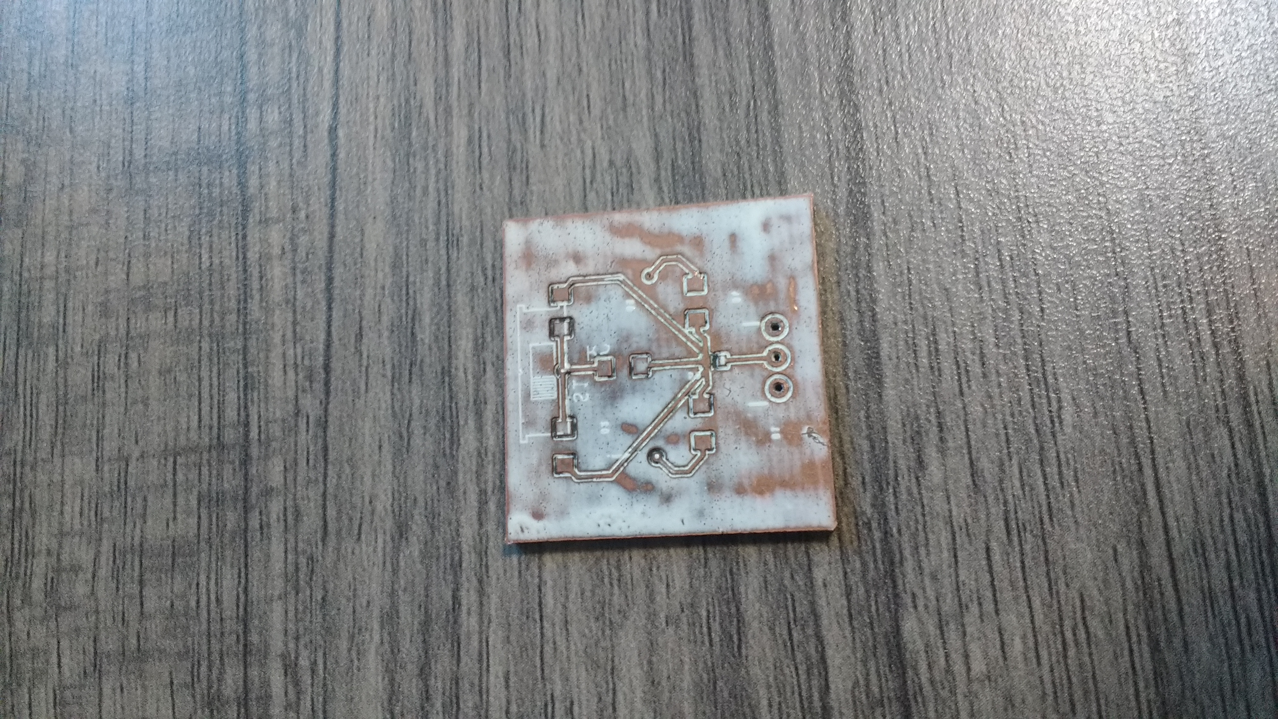
PCB - top
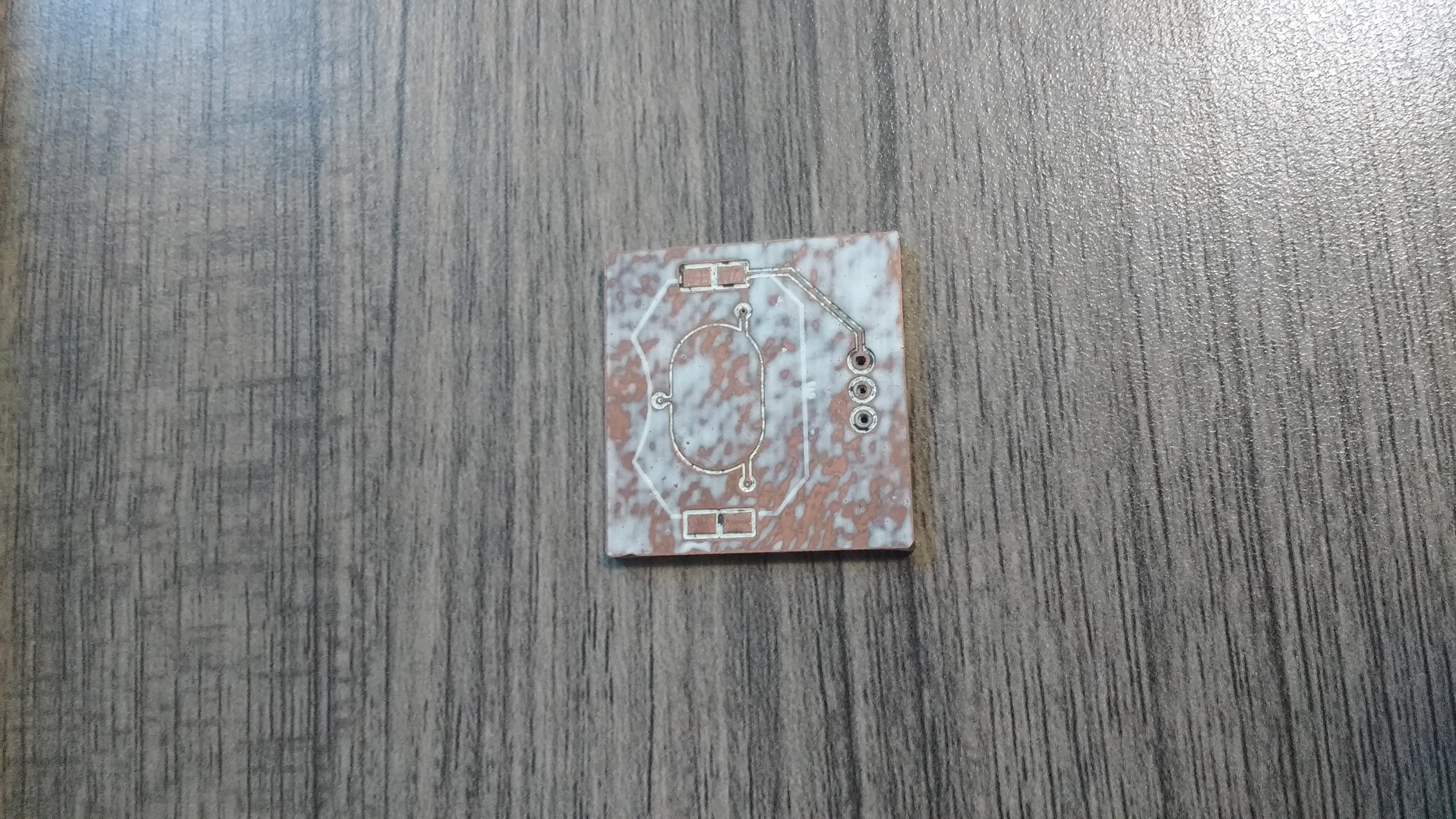
PCB - bottom
Second board - poorly designed, with manufacturing defects
For the second board, we had it printed without a silkscreen. Unfortunately at the time the E5 facility still couldn’t provide soldermasking. Nevertheless, we attempted to solder on components. This proved very difficult, since our resistor and leds were very small. We were able to solder the resistors and leds, but the battery holder was too tricky to solder, and the lack of soldermasking resulted in solder getting stuck all over the board. We also realized that the vias were defective. Back to square one.
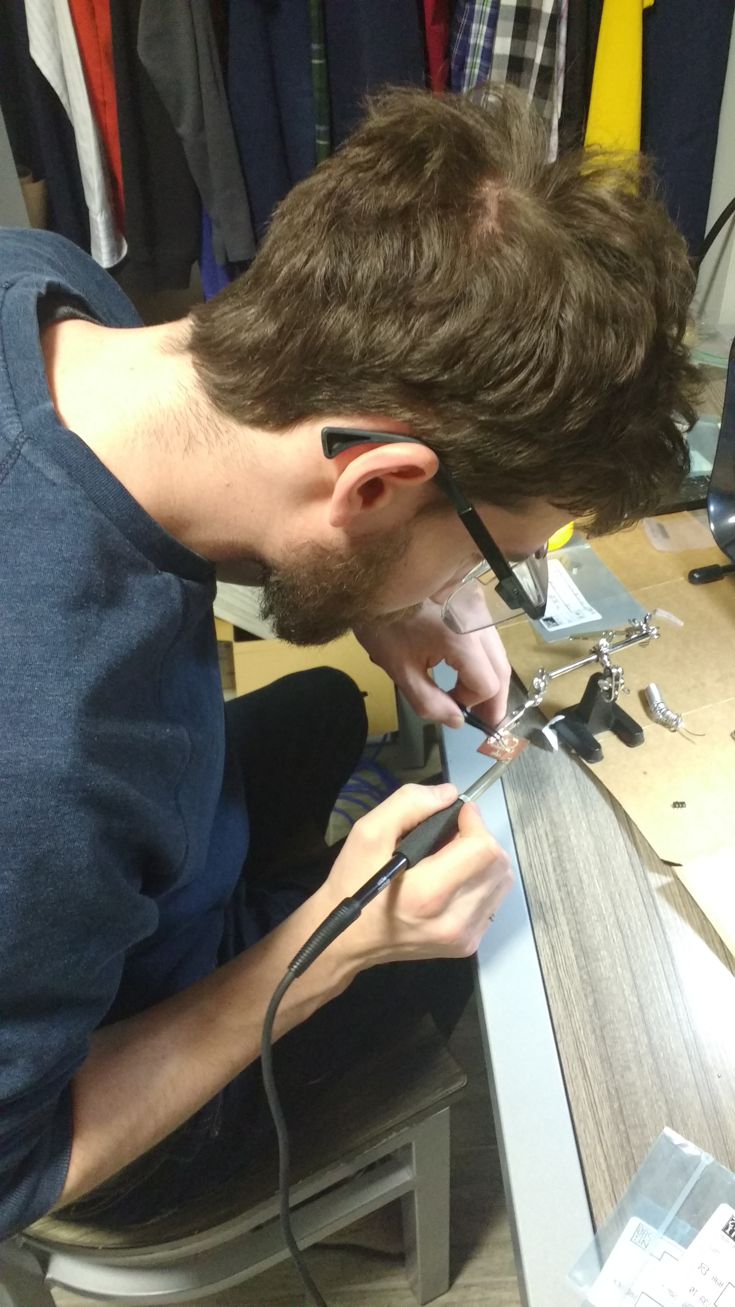
Lior with surgeon-like hands patiently solders a miniscule resistor to the board
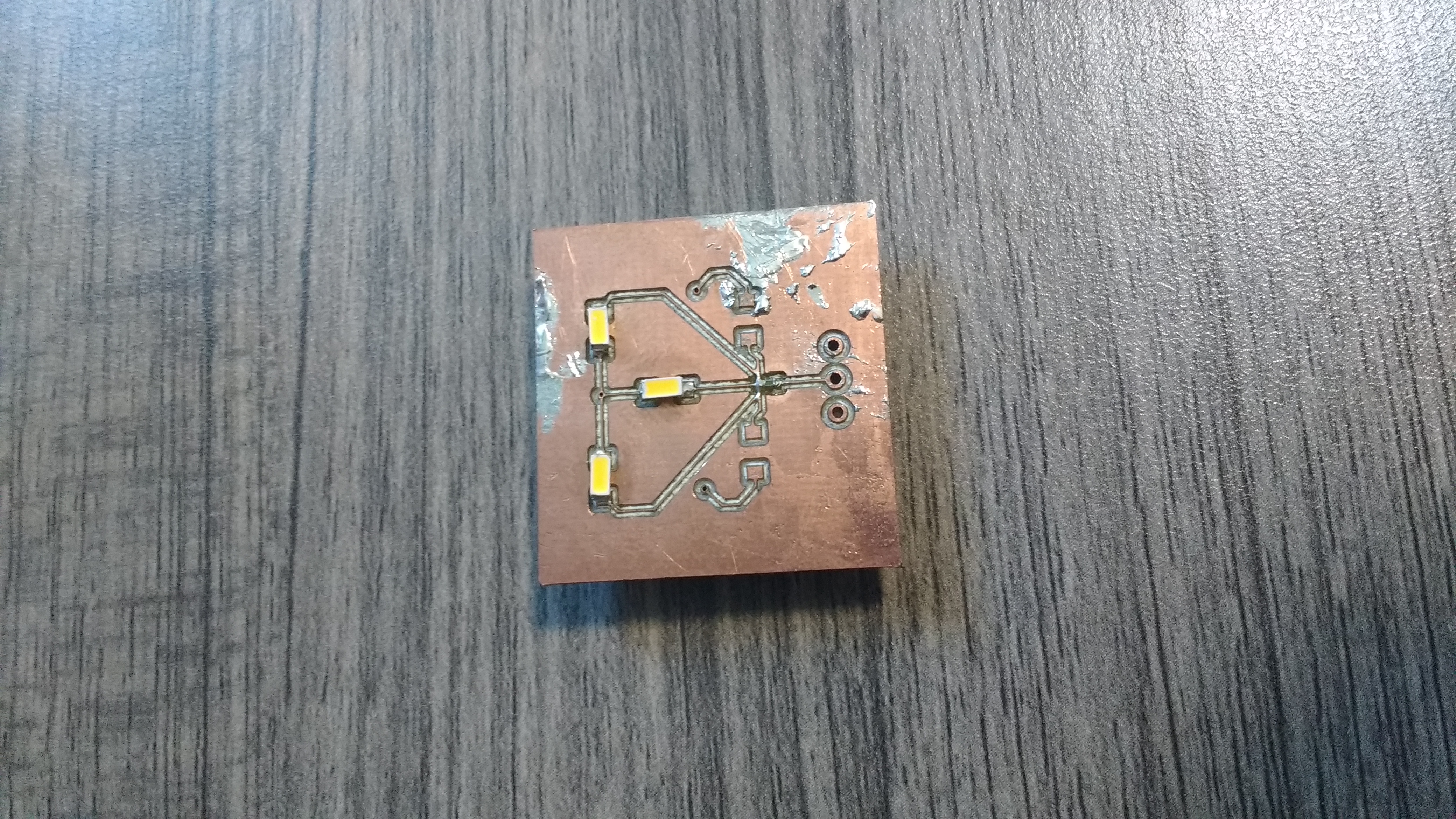
The end result - top
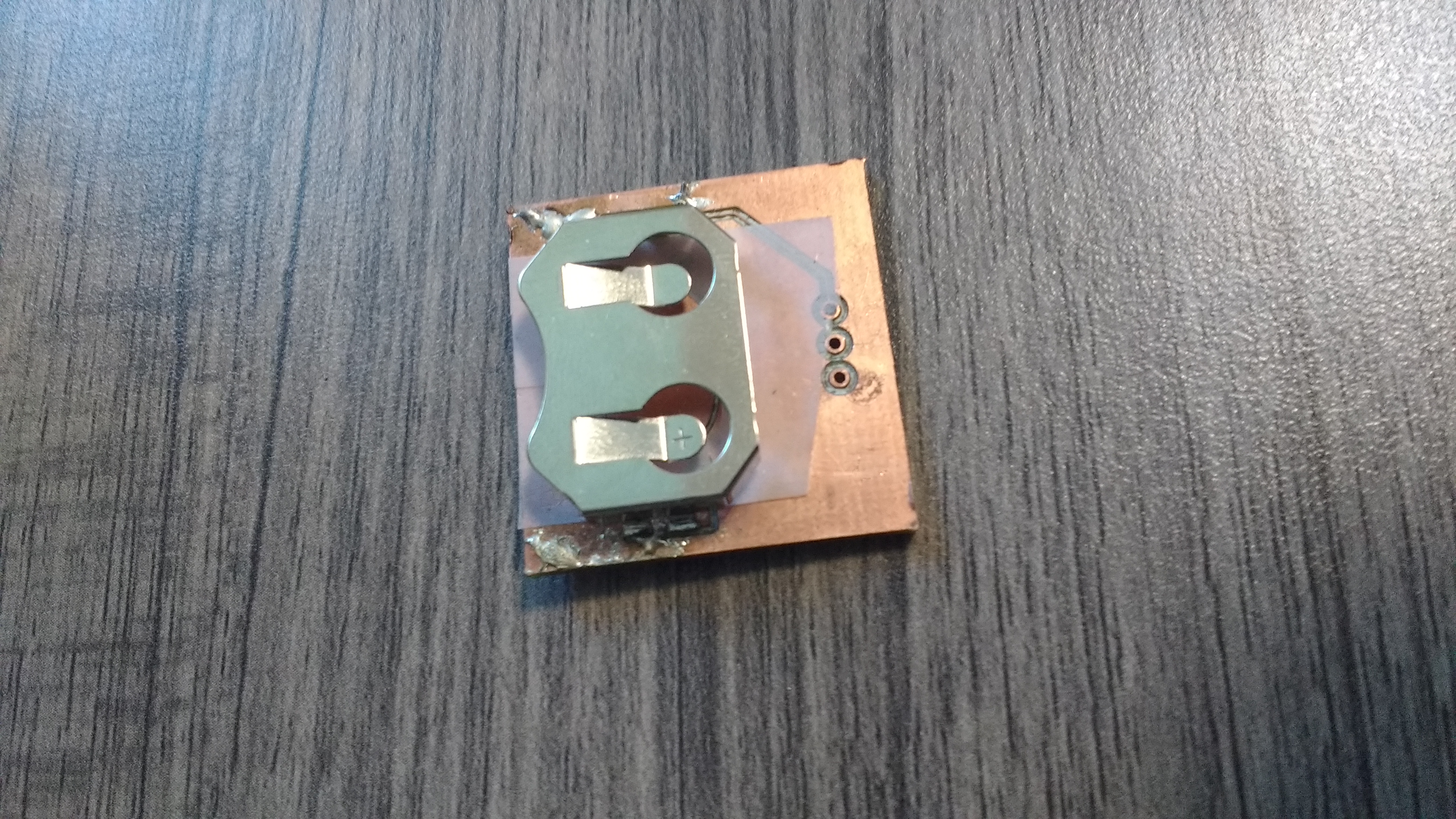
The end result - bottom
Third board - a new hope
For our third board, we bought larger, 1206 sized resistors, and made the pads for everything larger. As well, we used a more suitable plastic battery mount, that provides much better insulation for the battery, and easier-to solder contacts. We also replaced the vias with larger plated through-holes. Finally, the E5 facility was able to print it with solder masking. This new board should be much easier to hand solder, and hopefully we can use it to do more in depth testing in different lighting environments.
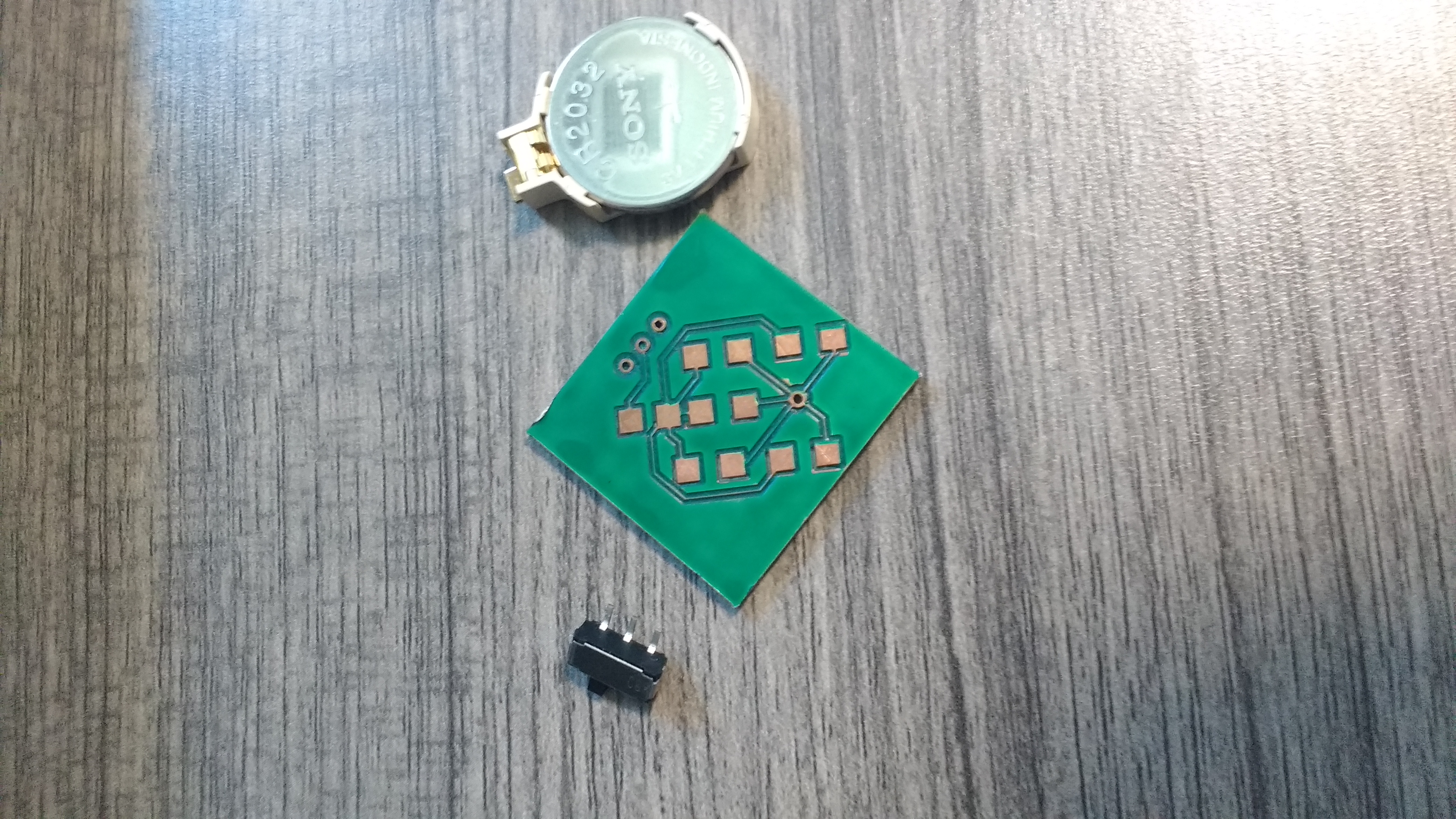
PCB V3 - top
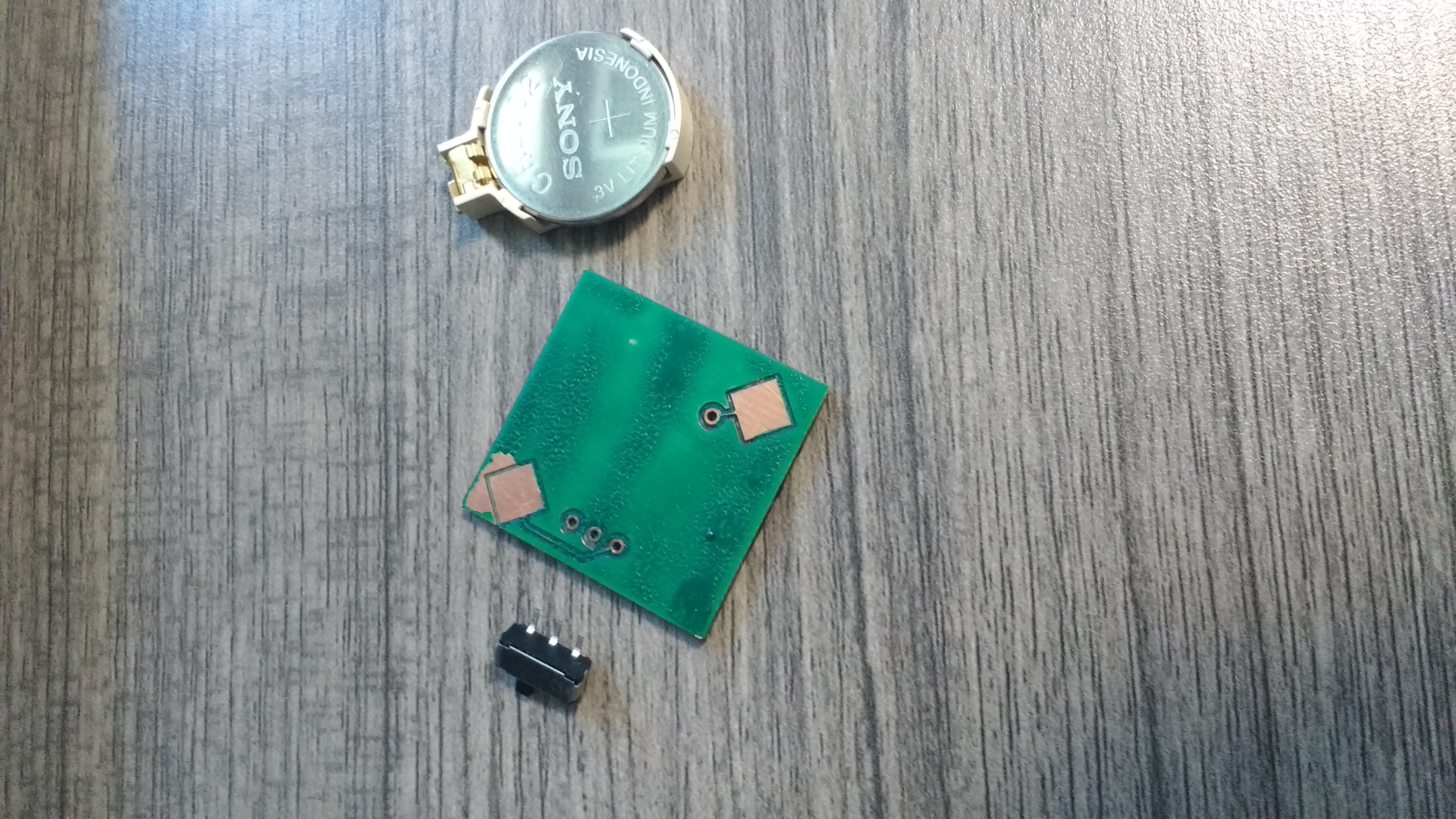
PCB V3 - bottom